RCD Programmer
 |
|
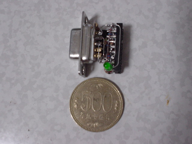
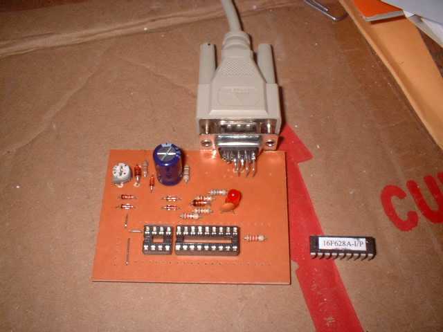
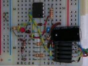
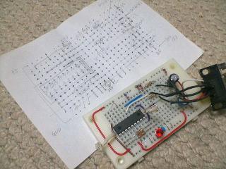
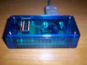
I built a "dongle" type RCD Programmer.
|
|
|
I built a "dongle" type RCD Programmer.
|
[Home]
 |
|
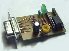
A RCD Programmer which I always use.
|
I believe that the "JDM Programmer" is cheap and very useful PIC Programmer. However, since "JDM Programmer" cannot control VDD, the algorithm "VPP before VDD" is inapplicable. Programming to the latest device from this reason may go wrong when using CONFIG settings as "Internal oscillator" "MCLR OFF". These devices are given power from the "JDM programmer",and execute program code. An error may come out by verification, or it may become impossible erasure and become impossible re-programming . In order to solve this problem, I designed a programmer based on the "JDM programmer." Since this programmer was made of resistors, capacitors, and diodes, I named this the "RCD Programmer." "Hardware settings" of IC-Prog are the same as the "JDM programmer."
 |
|
I think that the same problem still exists about programming other devices. (added: 2005-02-06 JST) |
C1 is a charge pump capacitor*. This works voltage doubler. When TxD is negative voltage, C1 is charged through D7 from GND. If TxD carries out turn-on, since it will become positive voltage, the voltage charged in C1 is raised. The created high voltage is regulated by D7 to about 13V. If TxD carries out turn-on, both supply voltage will be created. CTS and RTS also join creation of supply voltage. This VDD is delayed and is applied by C2 and R4. D1-D5 are clump diodes. Since voltage drop is within the limits which can be disregarded, general purpose small rectifier is sufficient as the diode to be used. e.g. 1N4148,1S1588(Toshiba),1S2076A(Renesas or Hitachi),1S133(ROHM) . When not succeeding by the device which needs programming current like 16F84(A), the value of R3 is made small. Probably, it will be good using a trimmer resistor as R3.
After I published the RCD Programmer on my Web site, it has passed in one year. I obtained various questions about the RCD Programmer from many people. And Microchip newly developed Low-Pincount PICs which built in the memory exceeding 1k words. I recommend change capacity of C1 to 470uF now for stable programming.
*About general description of charge pump, please refer to DC/DC Conversion without Inductors(Maxim/Dallas Application Note 725). A important point is not a charge pump but controll of VDD in the RCD Programmer circuit. If this point is excluded, the JDM Programmer is far more excellent than the RCD Programmer. Because the RCD Programmer works by the pulse only once, the capacitor power cannot be continued for a long time.
Consideration for the computers which have poor surge protection (added: 2005-02-06 JST)
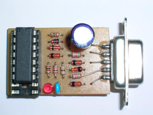
When you insert a RCD Programmer into the COM port of your computer during operation("Hot Plug-in" or "Hot Socketing"), inrush current is generated. It seems that it is weak to an overcurrent and a short circuit although "EIA/TIA -562" is power saving and compatible with "EIA/TIA-232-E." So, I added 200-ohm current limitation resistor. This resistor limits peak current and help computers which have poor surge protection circuit inside. However, the RCD programmer will not work well as for such a computer because the voltage of the COM port might be very low.
 |
 |
|
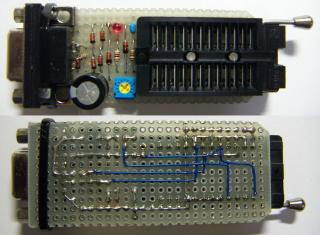
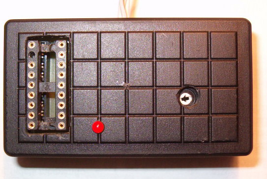
RCD Programmer for the computers whitch have poor surge protection
|
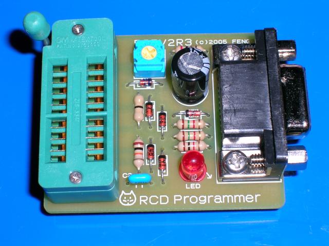
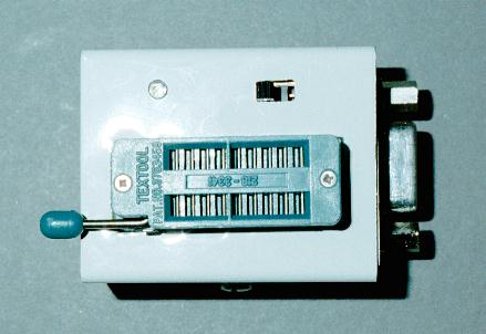
RCD Programmer with 18-pin TEXTOOL(3M)
|
|
Device
|
Code Mem
|
Required Voltage
|
IC-Prog
|
WinPic
|
PICProg4U | |||
|
Name
|
Words
|
on MCLR
|
100uF
|
470uF
|
100uF
|
470uF
|
470uF
|
Note
|
| PIC10F200F629 |
256x12
|
12.5 <= VPP <= 13.5
|
N/A
|
N/A
|
N/A
|
N/A
|
R
|
(3)
|
| PIC10F202F629 |
512x12
|
12.5 <= VPP <= 13.5
|
N/A
|
N/A
|
N/A
|
N/A
|
R
|
(3)
|
| PIC10F204F629 |
256x12
|
12.5 <= VPP <= 13.5
|
N/A
|
N/A
|
N/A
|
N/A
|
R
|
(3)
|
| PIC10F206F629 |
512x12
|
12.5 <= VPP <= 13.5
|
N/A
|
N/A
|
N/A
|
N/A
|
R
|
(3)
|
| PIC12F508F629 |
512x12
|
12.5 <= VPP <= 13.5
|
J
|
J
|
N/A
|
N/A
|
R
|
|
| PIC12F509F629 |
1024x12
|
12.5 <= VPP <= 13.5
|
J
|
J
|
N/A
|
N/A
|
R
|
|
| PIC12F629F629 |
1024x14
|
VDD + 3.5 (Max 13.5)
|
J
|
J
|
C/R
|
C/R
|
R
|
|
| PIC12F635 |
1024x14
|
10 <= VPP <= 12
|
N/A
|
N/A
|
C/R
|
C/R
|
R
|
(1)
|
| PIC12F675 |
1024x14
|
VDD + 3.5 (Max 13.5)
|
J
|
J
|
C/R
|
C/R
|
R
|
|
| PIC12F683 |
2048x14
|
10 <= VPP <= 12
|
N/A
|
N/A
|
C/R
|
C/R
|
R
|
(2)
|
| PIC16F54 |
512x12
|
12.5 <= VPP <= 13.5
|
N/A
|
N/A
|
N/A
|
N/A
|
R
|
|
| PIC16F57 |
2048x12
|
12.5 <= VPP <= 13.5
|
N/A
|
N/A
|
N/A
|
N/A
|
R
|
(3)
|
| PIC16F59 |
2048x12
|
12.5 <= VPP <= 13.5
|
N/A
|
N/A
|
N/A
|
N/A
|
R
|
(3)
|
| PIC16F627 |
1024x14
|
VDD + 3.5 (Max 13.5)
|
J
|
J
|
C/J/R
|
C/J/R
|
R
|
|
| PIC16F627A |
1024x14
|
10 <= VPP <= 13.5
|
N/A
|
N/A
|
C/J/R
|
C/J/R
|
R
|
(3)
|
| PIV16F628 |
2048x14
|
VDD + 3.5 (Max 13.5)
|
N/A
|
J
|
C/J/R
|
C/J/R
|
R
|
|
| PIC16F628A |
2048x14
|
10 <= VPP <= 13.5
|
N/A
|
J
|
C/J/R
|
C/J/R
|
R
|
(3)
|
| PIC16F630 |
1024x14
|
VDD + 3.5 (Max 13.5)
|
J
|
J
|
C/J/R
|
C/J/R
|
R
|
|
| PIC16F636 |
2048x14
|
10 <= VPP <= 12
|
N/A
|
N/A
|
C/R
|
C/R
|
R
|
(1)
|
| PIC16F648A |
4096x14
|
10 <= VPP <= 13.5
|
N/A
|
J
|
N/A
|
C/J/R
|
R
|
(3)
|
| PIC16F676 |
1024x14
|
VDD + 3.5 (Max 13.5)
|
J
|
J
|
C/J/R
|
C/J/R
|
R
|
|
| PIC16F684 |
2048x14
|
10 <= VPP <= 12
|
N/A
|
N/A
|
R
|
R
|
R
|
(1)
|
| PIC16F688 |
4096x14
|
10 <= VPP <= 12
|
N/A
|
N/A
|
N/A
|
C/R
|
R
|
|
| PIC16F818 |
1024x14
|
VDD + 3.5 (Max 13.5)
|
J
|
J
|
C/J/R
|
C/J/R
|
R
|
(4)
|
| PIC16F819 |
2048x14
|
VDD + 3.5 (Max 13.5)
|
J
|
J
|
C/J/R
|
C/J/R
|
R
|
(4)
|
| PIC16F84 |
1024x14
|
12 <= VPP <= 14
|
J
|
J
|
N/A
|
N/A
|
N/A
|
|
| PIC16F84A |
1024x14
|
12 <= VPP <= 14
|
J
|
J
|
N/A
|
N/A
|
R
|
(5)
|
| PIC16F87 |
4096x14
|
VDD + 3.5 (Max 13.5)
|
N/A
|
N/A
|
J
|
J
|
R
|
|
| PIC16F88 |
4096x14
|
VDD + 3.5 (Max 13.5)
|
J
|
J
|
J
|
J
|
R
|
|
|
Color
|
Pincount
|
Color
|
Results
|
Mark
|
Interface Setting
|
||
|
6/8-pin
|
Success
|
J
|
JDM Programmer 2
|
||||
|
14-pin
|
Passable
|
C
|
COM 84
|
||||
|
18/28/40- pin |
Failure
|
R
|
RCD Programmer
|
(1)WinPic-- When both IntOSC and internal MCLR options are selected, programming is successful satisfactory. However, after exiting Program/Verify mode, the device may be unable to be read(or verify) correctly. Please feel easy ! The device can be Re-programmed.
(2)The Device ID of PIC12F683 is 0x0460. ID value "0x1280" shown in the data sheet(DS41204C) is not corrected for now(corrected in the autumn of 2004, DS41204D).
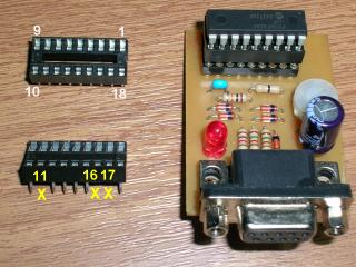
(3)Use an Adaptor, or ICSP Method for these devices ! Adaptor for SOT23 PIC10F2xx(example), for PIC16F57(example), for PIC16F627A/628A/648A( See photo below).
(4)WinPic-- Enable WinPic 's option "raise Vdd before MCLR=Vpp" !
(5)WinPic-- Don't use WinPic to programming to PIC16F84A with RCD Programmer! Use IC-Prog or PICProg4U!
Note:WinPic--The erasure and the re-programming might become impossible as for the devices afterwards when both IntOSC and internal MCLR options are selected besides by using WinPic that sets "InterfaceType" to "JDM Programmer 2". In that case, please try after clearing all the check boxes in "Interface Test".
The trick of programming PIC12F508/509 using IC-Prog
| How to make an adaptor for PIC16F627A/628A/648A. | ||||||
 |
||||||
| Use a cheap 18 pin IC socket.
Cut away these three pins(No.11,No.16 and No.17)of a 18 pin IC Socket. Insert this simple adapter between a device and a RCD programmer's IC socket. |
||||||
IC-Prog Author: Bonny Gijzen
WinPic Author: Wolfgang Büscher
PICProg4U Author: FENG3
Requires .NET Framework 1.1 or later.
The available COM port and the RCD Programmer are detected automatically.
Supported devices are PIC10F200/202/204/206/220/222, PIC12F508/509/510, PIC16F54/57/59, PIC12F629/635/675/683, PIC16F627/628, PIC16F627A/628A/648A,PIC16F630/636/639/676, PIC16F684/685/687/688/689/690, PIC16F818/819, PIC16F84A, PIC16F87/88, PIC16F870/871/872/873/874/876/877, PIC16F873A/874A/876A/877A.)
English version is available now!
Spanish version is available now!
Chinese version is available now!
Probably you should read "OSCCAL(internal OSCillator CALibration) word" and "BG(BandGap calibration) bits" in a device first, and should make a note of them on a piece of paper, before you start programming, so that it may not erase accidentally.
All OTP(One Time Programmable) devices and greater than 18-pin devices are not suppoerted !
PCB and other files (PDF format) can be downloaded from here.
"Dongle" type RCD Programmer
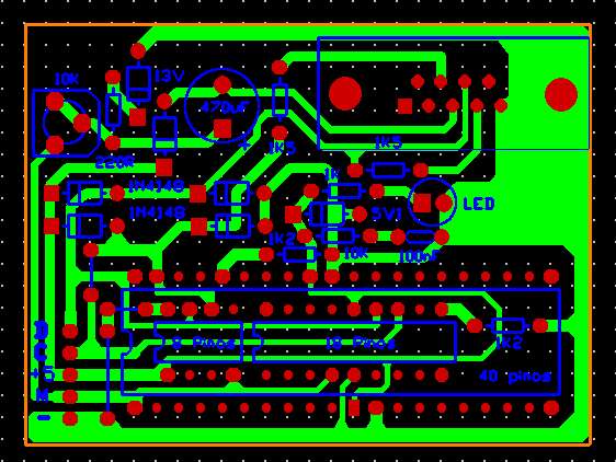
Note: J5 is a jumper wire or a jumper resistor.
PCB Components layout
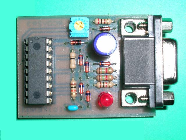
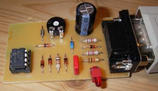
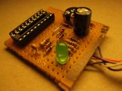
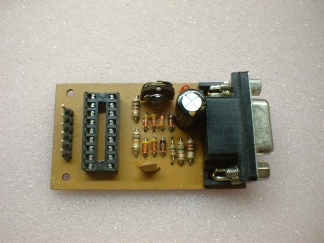
RCD Programmer which I always use
This board requires a 90°printed board mount D sub connector and a trim resistor. It is the size which can also mount 18pin TEXTOOL. Note: "0R" is a jumper wire or a jumper resistor.
PCB Components layout Bill Of Material
RCD Programmer for the computers whitch have poor surge protection
PCB Components layout Bill Of Material
..........................................................................................................
If a PDF file prints smaller or larger than expected (for example, 90% of the original size) from an Adobe Acrobat product (Adobe Reader an Adobe Acrobat), Do one or more of the following:
..........................................................................................................
|
by KTaro |
by VIC
|
by Oga
|
||||||||||||||
 |
 |
 |
||||||||||||||
|
by Takepyon
|
by Airband
|
by Filia Sofia
|
||||||||||||||
 |
||||||||||||||||
 |
 |
|||||||||||||||
|
by Alexandre Costa
|
PCB layout by Alexandre
|
by Helmut Stettmaier
|
||||||||||||||
 |
 |
 |
||||||||||||||
|
by Henri |
by Sven-Erik Ottosson |
|||||||||||||||
|
by Momoji
|
||||||||||||||||
 |
||||||||||||||||
 |
 |
|||||||||||||||
|
by Stefan Pietzonke
|
by Daniel José Viana
|
|||||||||||||||
 |
 |
|||||||||||||||
|
PCB layout (Eagle file)
by Daniel José Viana |
||||||||||||||||
[Home]
Last modified: 2008-09-21 JST
2004-03-06 JST